DMX RGB LED Fixture
Brian Neltner found me through this website and contacted me. He was in Boulder for postdoctoral work and was able to show me his cool Light Brick project. He has designed a completely open-sourced hobby high-brightness RGB LED fixture using 4 each Phillips Lumiled Rebel LEDs. His system uses a WiFi shield on an Arduino to IP-enable the fixture. I thought it might be useful to provide an open-source DMX interface for the fixture using Max Pierson’s Arduino DMX receiver code (rev15).
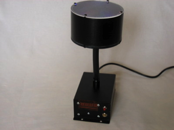
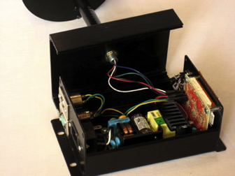
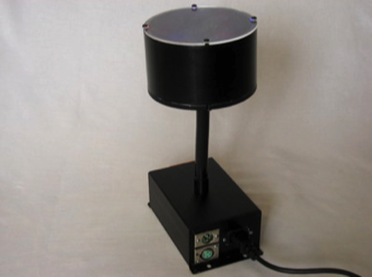
The fixture is built in a machined aluminum enclosure to match Brian's design. It contains a 24 VDC 2.5A power supply and custom hand-wired Arduino controller board. Features include:
- 4 digit 7-segment multiplexed LED display of DMX channel or current program.
- Unique control interface consisting of a button and potentiometer.
- 5-channel DMX operation: mode, master intensity and 3 color channels.
- 4 programs in addition to DMX operation: Manual color, strobe, sequential fade, random fade.
- EEPROM storage of DMX address and program.
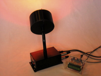
Fixture Connections
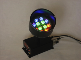
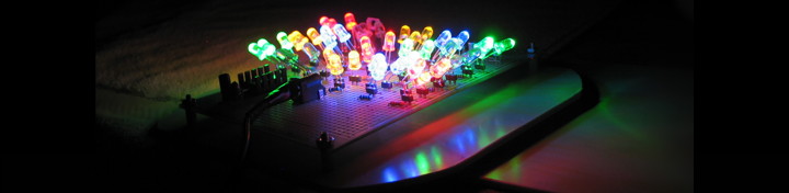
Fixture LEDs
Operation
The fixture is mode based and may be operated from the DMX interface or through a built-in program. The mode is selected using the button.
- DMX Operating mode: The fixture is operated using the DMX interface.
- DMX Address mode: Allows the user to select the starting DMX address (1-506). The potentiometer is used to set the value of each address digit (ones, tens and hundreds).
- Program 1: Allows the user to manually set the fixture color using the potentiometer.
- Program 2: Allows the user to select a strobe speed using the potentiometer (and color selected by program 1).
- Program 3: Allows the user to select the speed using the potentiometer for a continuous sequential fade through the color spectrum: red -> yellow -> green -> cyan -> blue -> magenta -> red.
- Program 4: Allows the user to select the speed using the potentiometer for a random fade between various colors. The random algorithm is biased to select between moderately and fully saturated colors.
The address and current operating mode are stored in EEPROM. In addition the fixture color set while in Program 1 is stored so that it is properly recalled if the stored program is 2 (strobe).
Controls
Push Button: Selects mode.
- Short press (less than two seconds) moves between operating modes: DMX Operation -> Program 1 -> Program 2 -> Program 3 -> Program 4 -> DMX Operation.
- Long press (more than two seconds) in DMX Operating mode selects DMX Address mode to change the current address. A short press in DMX Address mode moves between digits to modify. A long press exits back to DMX Operating mode.
Potentiometer: Mode dependent.
- DMX Operating mode: Unused
- DMX Addressing mode: Sets the current digit value (ones, tens or hundreds). The digit value depends on the position of the pot. Digit values are not changed until the pot is changed.
- Program 1: Sets the fixture color: black -> white -> red -> yellow -> green -> cyan -> blue -> magenta -> red.
- Program 2: Sets the strobe speed: 1 - 33 flashes/second.
- Program 3: Sets the fade speed: ~10 - 200 changes/second.
- Program 4: Sets the fade speed: ~10 - 200 changes/second.
LED Display: Mode dependent.
- DMX Operating mode "Cnnn": Displays the current starting DMX channel.
- DMX Addressing mode "Annn": Displays the new starting DMX channel. The digit being changed blinks. Although any address 1-999 may be set in this mode, the firmware limits the maximum starting address to 506 on exit from the mode.
- Program 1 "P 1": Indicates program 1.
- Program 2 "P 2": Indicates program 2.
- Program 3 "P 3": Indicates program 3.
- Program 4 "P 4": Indicates program 4.
DMX Channel
Channel Assignment:
- Mode
- Master Intensity
- Red Intensity
- Green Intensity
- Blue Intensity
- 0-63: DMX Color Control using Master, Red, Green, Blue channels.
- 64-127: Strobe using Master, Red, Green, Blue channels. The value sets the strobe speed from 1-33 flashes/second.
- 128-191: Sequential fade. The value sets the fade speed.
- 192-255: Random fade. The value sets the fade speed.
Notes
- DMX Timing seems to get a bit wonky at high addresses (close to the limit of 506). Could just be the cheap DMX console I have.
- Strobe timing seems to get a bit wonky at some strobe rates. I selected the strobe "on" time to correspond with a full PWM period but not all channels (red, green and blue) seem to operate together at some strobe rates.
- The circuit uses a FTDI USB cable to program the processor in-circuit. The 1 kohm pull-up resistor on the nRE line disables the SN75176 driver from driving the RX line during programming.
- The circuit allows for bidirectional communication on DMX (e.g. RDM) although that feature is not currently supported by the software.
- Use common-anode LED displays. The series limiting resistors on each segment must be chosen so that the maximum current through any anode is less than 40 mA (Min resistor value is 510 ohms).
- Make sure to use a linear potentiometer.
- The Light Brick fixture can get very warm. I added some thermally conductive grease between the fixture base and the tubular enclosure to improve heat-sinking of the LEDs.