
NRF PROG
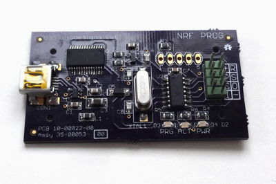
NRF PROG is a programmer for the Nordic Semiconductor nRF24LE1 SoC. This great chip combines a 2.4 GHz radio transceiver with an 8051 core, 16 KB flash memory, 1.25 KB RAM and IO peripherals. The radio is compatible with the ubiquitous nRF24L01+ transceiver that can be found on a large number of inexpensive Chinese manufactured boards. Nordic supports the chip with a typical (read: expensive) development environment with a programmer/debugger and commercial C compiler. Fortunately the SDCC team also supports the chip with their great C Compiler.
NRF PROG programs and reads the Flash memory on the nRF24LE1. It can also be used to execute any Flash Memory interface SPI Command. It drives the RESETN, PROG and Flash Interface SPI signals as well as supplies power. It is primarily designed for programming modules but can be used in-circuit if precautions are taken with signals shared with application circuitry.
I developed NRF PROG as part of my own work and decided to release it, along with a supporting computer-based control program, to support other developers using the nRF24LE1.
In addition to NRF PROG I developed a big-brother programmer designed for use in production environments. This programmer is for sale. Contact me for more information.
Downloads and Links
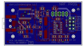
Design package including gerber files, firmware (source, hex), eagle CAD files, BOM and schematic in PDF form. Circuit design was done using Eagle 5.11. Firmware is PIC Assembly for the PIC16F1825 and can be assembled in MPLAB, programmed with a Microchip (or compatible) ICSP programmer.
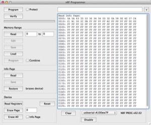
Link to page describing companion PC programmer software and downloads for Windows, OS X and Linux.
Link to a shared Mouser project with all parts for one board.
Link to a shared OSH Park project to order PCBs.
Link to the SDCC project page at sourceforge. SDCC runs on Windows, Linux and Mac OS X. I typically use the following compile options:
code-size can be changed to 0x4400 when programming the data EEPROM. The ihx files are converted to Intel Hex files using the packihx command.
--model-large --std-c99 --code-loc 0x0000 --code-size 0x4000 --xram-loc 0x0000 --xram-size 0x400 --noinvariantcode-size can be changed to 0x4400 when programming the data EEPROM. The ihx files are converted to Intel Hex files using the packihx command.
packihx filename.ihx > filename.hexBrennen Ball's website where he sells nRF24LE1 breakout boards and has a library of functions for using the device's on-board peripherals. His boards come with a built-in serial bootloader and he has his own utility for programming them but you can use NRF PROG if you don't want serial programming or need those extra bytes for your own code. His boards were a godsend when I started experimenting with the nRF24LE1.
Link to Nordic's SDK page. Designed for use with their development environment and the Keil compiler, it may still be helpful in understanding how to use various peripherals.
Operation
Connections
+
-
-
3.3V power for the nRF24LE1. Output from the FT232RL internal regulator and is limited to about 25 mA.
R
RESETN. Active low reset signal. Connect to the nRF24LE1 RESET pin.
P
PROG. Active high program enable signal. Connect to the nRF24LE1 PROG pin.
S
CSN. Active low chip select signal. Connect to the nRF24LE1 FCSN pin:
- 24pin - 4x4 version: P0.5
- 32pin - 5x5 version: P1.1
- 48pin - 7x7 version: P2.0
C
SCK. SPI Clock signal. Connect to the nRF24LE1 FSCK pin:
- 24pin - 4x4 version: P0.2
- 32pin - 5x5 version: P0.5
- 48pin - 7x7 version: P1.2
O
MOSI. SPI Master Out Slave In signal. Connect to the nRF24LE1 FMOSI pin:
- 24pin - 4x4 version: P0.3
- 32pin - 5x5 version: P0.7
- 48pin - 7x7 version: P1.5
I
MISO. SPI Master In Slave Out signal. Connect to the nRF24LE1 FMISO pin:
- 24pin - 4x4 version: P0.4
- 32pin - 5x5 version: P1.0
- 48pin - 7x7 version: P1.6
LED Indicators
PRG
PROG mode. Lit when PROG is asserted.
ACT
Blinks when a command is processed by the firmware.
PWR
Power. Lit when the FT232R has been enumerated and power enabled on the programmer.
Command Interface
The firmware running on NRF PROG provides a command/response interface between a program running on a personal computer and the nRF24LE1 SPI interface used for programming. The PC communicates via a serial interface (provided by a FTDI FT232RL USB-serial chip) at 115,200 baud (8N1). The firmware interprets a simple ASCII-based command set with two encoding forms. Each command generates a response. One command form is designed for use with an external program. The other command form is designed for use with a terminal emulator (and commands entered by hand).
Form 1: For use with programming software
'H'[HexCommand][HexData]'T'[HexChecksum]- The ASCII character 'H' is the packet start marker.
- [HexCommand] is a two ASCII character hex command (see below).
- [HexData] is command-specific, optional, data representing one or more bytes (up to 256) comprised of two ASCII character hex numbers for each byte.
- The ASCII character 'T' is the packet end marker. It indicates this is Form 1 and requires a checksum byte to follow.
- [HexChecksum] is a two ASCII character hex checksum (the Sum of all character bytes 'H' to 'T' inclusive).
- No other characters should be included in the packet for performance reasons. The firmware will ignore ASCII space characters and
(Carriage Return - 0x0D - Ctrl-L) characters.
Form 2: For use with a terminal
'H'[HexCommand][HexData][LF]- The ASCII character 'H' is the packet start marker.
- [HexCommand] is a two ASCII character hex command (see below).
- [HexData] is command-specific, optional, data representing one or more bytes (up to 256) comprised of two ASCII character hex numbers for each byte.
- The ASCII character [LF] (Linefeed - 0x0A - Ctrl-J> is the packet end marker. It indicates this is Form 2 and does not require a checksum to follow.
- ASCII space characters and [CR] (Carriage Return - 0x0D - Ctrl-L) characters are ignored between 'H' and [LF].
All hex values are expressed as two-character strings comprised of the ASCII characters '0' - '9' and 'A' - 'F' or 'a' - 'f'. All characters between the end-of-packet (or checksum for Form 1) and the next start-of-packet character 'H' are ignored.
There are two response forms. The NACK and ACK responses are formatted slightly differently depending if the original command was Form 1 or Form 2.
HexCommand Values
0x00 ("00")
Version. Firmware identifier and version.
- No HexData bytes.
- Returns three bytes with ACK:
[TYPE][MAJOR][MINOR]
- TYPE : Firmware type (0x01 for this firmware)
- MAJOR : Major revision. Incremented when new functionality is added.
- MINOR : Minor revision. Incremented for bug fixes.
0x01 ("01")
Access Mode. Controls entry and exit from program mode. Entering access mode causes the following actions to occur:
Takes one byte of HexData.
- Assert the PROG signal to the nRF24LE1.
- Assert the nRESET signal to the nRF24LE1 for > 0.2 uSec.
- Enables the SPI interface to the nRF24LE1.
- Waits 1.5 mSec before returning a response.
- Disables (tri-states) the SPI interface to the nRF24LE1
- De-asserts the PROG signal to the nRF24LE1
Takes one byte of HexData.
- Bits 7:1: Reserved: Set to 0.
- Bit 0: Program Mode (1 = enter program mode; 0 = exit program mode)
0x02 ("02")
SPI Command. Used to send SPI commands to the nRF24LE1 programming interface (such as WREN, ERASE PAGE, etc).
- 1 - 256 HexData bytes. The first byte is the nRF24LE1 SPI Command. Subsequent bytes are any required data for the command.
- Returns an equal number of response bytes, one for each data byte, with ACK.
0x03 ("03")
Set Address. Used to set the starting address for subsequent Program or Read Memory commands.
- Two HexData bytes:
[ADDRESS15:8][ADDRESS7:0] - Returns no response bytes with ACK.
0x04 ("04")
Program Memory. Program and verify a series of data bytes starting with the current address (may be initialized with the Set Address command). Executes the following sequence of operations:
- Execute the WREN SPI Command sequence.
- Execute the PROGRAM SPI Command with the data bytes.
- Poll FSR using RDSR SPI Command for write to finish.
- Verify data using the READ SPI Command.
- Update current address to point to the next address location past the last data byte
- 1 - 256 HexData bytes
- Returns one byte, status, with ACK.
0x05 ("05")
Read Memory. Read a series of data bytes starting with the current address.
- One HexData byte indicating read length (value 0 - 255 for 256, 1-255 bytes).
- Returns 1-256 read data bytes with ACK.
- Update current address to point to the next address location past the last read byte.
0x06 ("06")
Reset. Pulse the reset signal. Designed to be used with the programmer attached to a functioning device (not in PROG mode).
- No data bytes.
- Returns no response bytes with ACK.
Response Values
NACK response for commands that have failed:
- Form 1:
'X'[HexNackCode]'T'[HexChecksum] - Form 2:
'X'[HexNackCode][CR][LF]
- "00" : Unknown command
- "01" : Not in access mode
- "02" : Command packet checksum error (for Form 1 commands only)
- "03" : Malformed command packet
- "04" : Illegal number of arguments
- Form 1:
'R'[HexData]'T'[HexCheckSum] - Form 2:
'R'[HexData][CR][LF]
Notes
- Access mode must be enabled before executing any commands that use the SPI interface. A NACK response is generated otherwise.
- Configuring reads/programming writes to the InfoPage must be configured through a SPI command to execute the WRSR SPI command.
- Care should be taken when connecting the programmer to the circuit to be programmed as shorts or voltage droops due to capacitive loading can reset the FT232R and disconnect it from the driver running on the PC.