
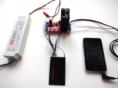
Touch Potentiometer Stereo Volume Control
Replacing a traditional potentiometer in the Sparkfun amplifier kit powered at 12VDC. The Touch Potentiometer is configured with the logarithmic transfer function on the analog output and connected between the input signals and amplifier.
Some care is taken to reduce noise produced by the digital sections of the Touch Potentiometer.
This example is shown with the original Touch Potentiometer. The Sparkfun version does not require the additional voltage regulator (although you should keep the 180 ohm resistor between 12VDC and the VIN terminal)
Some care is taken to reduce noise produced by the digital sections of the Touch Potentiometer.
- Provide additional filtering on the logic supply.
- Isolate the digital and analog sections.
This example is shown with the original Touch Potentiometer. The Sparkfun version does not require the additional voltage regulator (although you should keep the 180 ohm resistor between 12VDC and the VIN terminal)
(Yeah...I know...a switching power supply...)
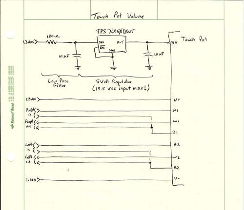
Both V+ and the input to the voltage regulator filter are connected to the +12VDC input of the amplifier. J1 is removed on the Touch Potentiometer
The V- input is connected to the GND input of the amplifier. J2 remains connected on the Touch Potentiometer for the digital ground.
The wiper and B signals are connected to the potentiometer wiper and ground pads on the amplifier.
The V- input is connected to the GND input of the amplifier. J2 remains connected on the Touch Potentiometer for the digital ground.
The wiper and B signals are connected to the potentiometer wiper and ground pads on the amplifier.
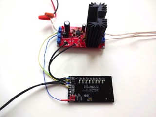
A SOT23-5 voltage regulator and two 10 uF capacitors are mounted to an adapter board stuck to the Touch Potentiometer with double-sticky tape. The input filter resistor is protected by shrink wrap tubing.
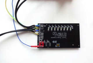
The audio input signal is connected to the Touch Potentiometer A signals. The grounds are connected to the B signals.
Note: J1 removed. J2 installed.
The audio input signal is connected to the Touch Potentiometer A signals. The grounds are connected to the B signals.
Note: J1 removed. J2 installed.