NRF PROG 2
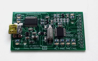
NRF PROG 2 is a production programmer for the Nordic Semiconductor nRF24LE1 SoC.
NRF PROG 2 programs and reads the Flash memory on the nRF24LE1. It can also be used to execute any Flash Memory interface SPI Command. It drives the RESETN, PROG and Flash Interface SPI signals as well as supplies power. It is designed to be integrated into a programming fixture and provides features for a manufacturing environment including:
NRF PROG 2 programs and reads the Flash memory on the nRF24LE1. It can also be used to execute any Flash Memory interface SPI Command. It drives the RESETN, PROG and Flash Interface SPI signals as well as supplies power. It is designed to be integrated into a programming fixture and provides features for a manufacturing environment including:
- Power control of the device being programmed. Switches power on after programming is initiated and off when programming is finished to allow safe removal of the device from the programming fixture.
- Auto-trigger for programming. For example a button integrated in the test fixture that is pressed when a board is installed.
- Pass/Fail indicator lights and outputs. Green Pass indicator, Red Fail indicator. Outputs may be connected to LEDs integrated in the programing fixture.
Price: $50 + shipping
Contact me for payment via paypal and to arrange shipping details.
Contact me for payment via paypal and to arrange shipping details.
Downloads and Links
Link to page describing companion PC programmer software and downloads for Windows, OS X and Linux. Automatically detects NRF PROG 2 and enables auto-programming and pass/fail indication functionality.
NRF PROG 2 schematic.
Link to the SDCC project page at sourceforge. SDCC runs on Windows, Linux and Mac OS X. I typically use the following compile options:
code-size can be changed to 0x4400 when programming the data EEPROM. The ihx files are converted to Intel Hex files using the packihx command.
--model-large --std-c99 --code-loc 0x0000 --code-size 0x4000 --xram-loc 0x0000 --xram-size 0x400 --noinvariantcode-size can be changed to 0x4400 when programming the data EEPROM. The ihx files are converted to Intel Hex files using the packihx command.
packihx filename.ihx > filename.hexBrennen Ball's website where he sells nRF24LE1 breakout boards and has a library of functions for using the device's on-board peripherals. His boards come with a built-in serial bootloader and he has his own utility for programming them but you can use NRF PROG if you don't want serial programming or need those extra bytes for your own code. His boards were a godsend when I started experimenting with the nRF24LE1.
Link to Nordic's SDK page. Designed for use with their development environment and the Keil compiler, it may still be helpful in understanding how to use various peripherals.
Operation
Connections
+
-
-
3.3V power for the nRF24LE1. Output from the FT232RL internal regulator and is limited to about 25 mA. Controlled by the nrf_prog software. Switched on during programming and verification when the program is configured for auto-programming. Switched on when nrf_prog is connected to the programmer and auto-programming is disabled.
B
Trigger Button Input. Active low signal designed to be connected to a button that is depressed when the board to be programmed is inserted into a programming fixture and is making contact with spring-loaded pins connecting the programming signals to the nRF24LE1 on the board.
1
PASS LED. Active low signal designed to connect to a LED cathode and current limiting resistor (360-1k ohm) on the test fixture if desired. The NRF PROG 2 also includes a green LED connected to this signal. Lit when a programming and verification sequence is successfully executed during auto-programming. Turned off when the Trigger Button Input is de-asserted (board removed).
2
FAIL LED. Active low signal designed to connect to a LED cathode and current limiting resistor (360-1k ohm) on the test fixture if desired. The NRF PROG 2 also includes a red LED connected to this signal. Lit when a programming and verification sequence does not successfully execute during auto-programming. Turned off when the Trigger Button Input is de-asserted (board removed).
R
RESETN. Active low reset signal. Connect to the nRF24LE1 RESET pin.
P
PROG. Active high program enable signal. Connect to the nRF24LE1 PROG pin.
S
CSN. Active low chip select signal. Connect to the nRF24LE1 FCSN pin:
- 24pin - 4x4 version: P0.5
- 32pin - 5x5 version: P1.1
- 48pin - 7x7 version: P2.0
C
SCK. SPI Clock signal. Connect to the nRF24LE1 FSCK pin:
- 24pin - 4x4 version: P0.2
- 32pin - 5x5 version: P0.5
- 48pin - 7x7 version: P1.2
O
MOSI. SPI Master Out Slave In signal. Connect to the nRF24LE1 FMOSI pin:
- 24pin - 4x4 version: P0.3
- 32pin - 5x5 version: P0.7
- 48pin - 7x7 version: P1.5
I
MISO. SPI Master In Slave Out signal. Connect to the nRF24LE1 FMISO pin:
- 24pin - 4x4 version: P0.4
- 32pin - 5x5 version: P1.0
- 48pin - 7x7 version: P1.6
LED Indicators
PWR (lower left)
Power. Lit when the FT232R has been enumerated and power enabled on the programmer.
PWR (upper right)
Device Power. Lit when nrf_prog has enabled power to the device being programmed.
ACT
Blinks when a command is processed by the firmware.
PRG
PROG mode. Lit when PROG is asserted.
PAS / FAIL
Programming PASS or FAIL indications for auto-programming mode.
TX / RX
FT232R status signals indicating serial communication with the computer.
Operation
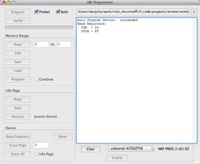
NRF PROG 2 provides a super-set of the functions in NRF PROG. The nrf_prog software program operates slightly differently when connected to the NRF PROG 2. It starts by displaying an additional checkbox called "Auto" that enables auto-programming. When checked this box enables the software to initiate programming whenever the Trigger Button on the fixture is pushed. In addition the "Protect" checkbox is checked by default when auto-programming is enabled to code-protect the firmware loaded into the nRF24LE1.
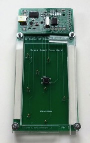
For auto-programming, the NRF PROG 2 should be part of a programming fixture that includes spring loaded pins that contact pads on the device's PCB connected to the nRF24LE1's programming pins. The fixture also includes the trigger button that is pressed when a PCB is inserted after contacting the spring-loaded pins. The programming sequence operates as follows when the trigger button is pressed.
When the "Auto" checkbox is unchecked, nrf_prog operates in the manual mode described on the NRF PROG page.
For auto-programming, the NRF PROG 2 should be part of a programming fixture that includes spring loaded pins that contact pads on the device's PCB connected to the nRF24LE1's programming pins. The fixture also includes the trigger button that is pressed when a PCB is inserted after contacting the spring-loaded pins. The programming sequence operates as follows when the trigger button is pressed.
- Power on the device to be programmed.
- Enter PROG mode.
- Program the firmware.
- Verify the firmware.
- Protect the firmware (if enabled).
- Power off the device to be programmed
- Indicate PASS or FAIL.
- Wait for the trigger button to be released.
- Turn off the PASS or FAIL indicator (ready for the next board).
When the "Auto" checkbox is unchecked, nrf_prog operates in the manual mode described on the NRF PROG page.